Magnetic Particle Inspection
The plane is cracking up…
Yes – but it’s no problem, as long as the crack propagation has not reached the uncontrolled phase yet. And to make sure that it hasn’t reached that stage, regular and systematic checks are not only advisable, but critically necessary. Not every crack is a problem, but some of them, especially cracks on the surface of dynamically loaded components, can be signs of dangerous part defects or failure. To decide which is the case, these cracks must be found and assessed.
Investigative results from any number of failure/damage reports have shown that it is primarily surface cracks which lead to part failure, as the surface is typically the site of the highest loads. In the past, an erroneous belief was widespread that every single crack or imperfection (no matter how tiny) would eventually lead to part failure; nowadays, the principles of fracture mechanics together with improved knowledge of material toughness and extensive experimental data (such as that surrounding Airbus wings, among others) have shown us that this is not necessarily the case. Nonetheless, the problem of finding and identifying cracks, and (more importantly) determining their potential to be lethal, is the first order of business for non-destructive material and component testing.


Magnetic Particle Inspection acc. to DIN EN 1369
For ferromagnetic materials – such as the standard cast iron materials (with the exception of the austenitic grades) – the magnetic powder crack test (according to DIN EN 1369 (2013-01) is the first choice in terms of cost and practicability, especially since it is much more sensitive, faster and more clearly as the Dye Penetrant Inspection. The method is based on the field displacement caused by cracks, blowholes, slag lines and similar faults, where the higher magnetic resistance must be compensated by increasing the passage cross section, allowing lines of force to escape from the workpiece, if the fault occurs or just below the surface (2 – 3 mm).
Magnetisation of iron parts
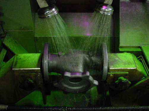
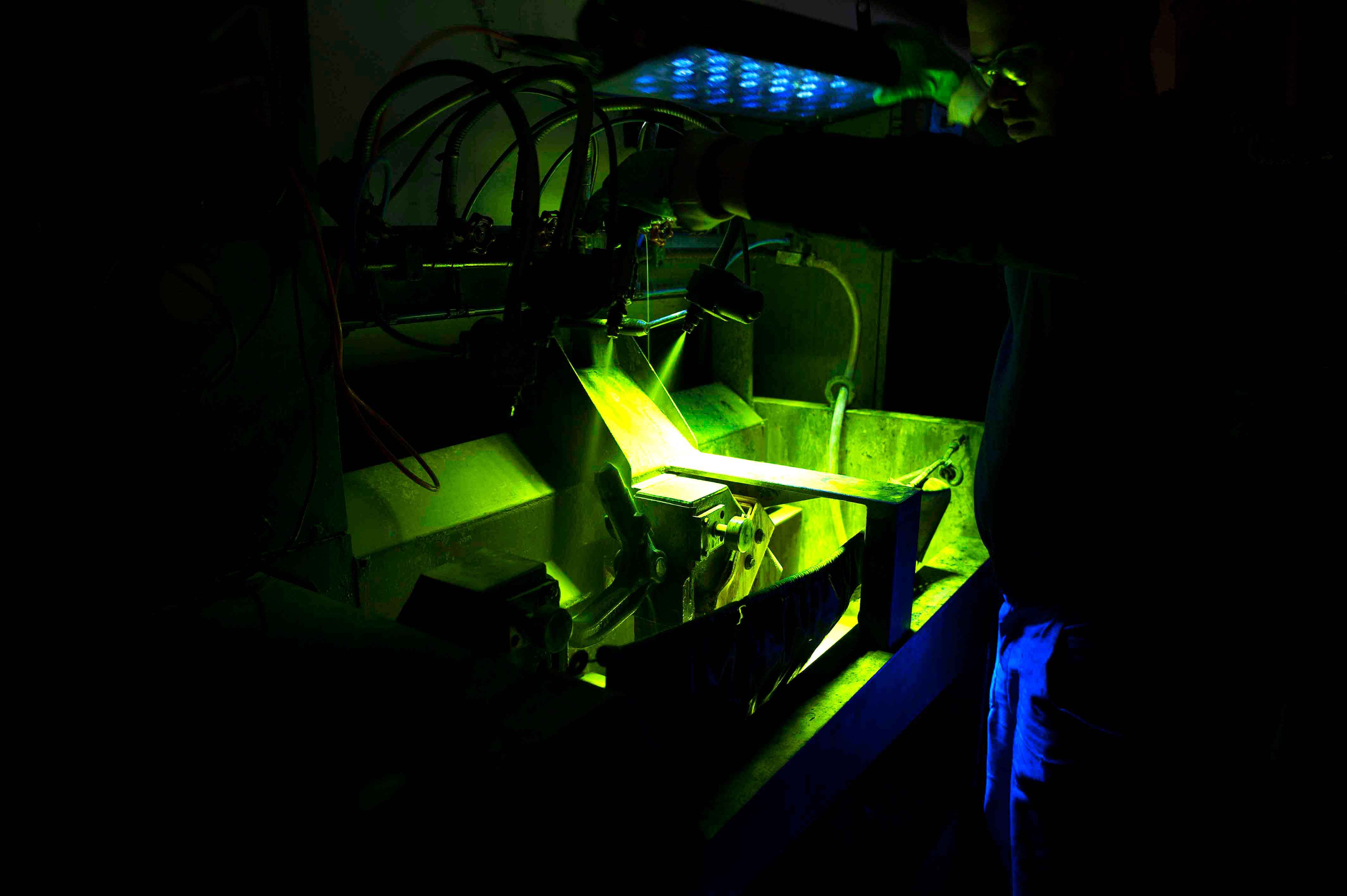
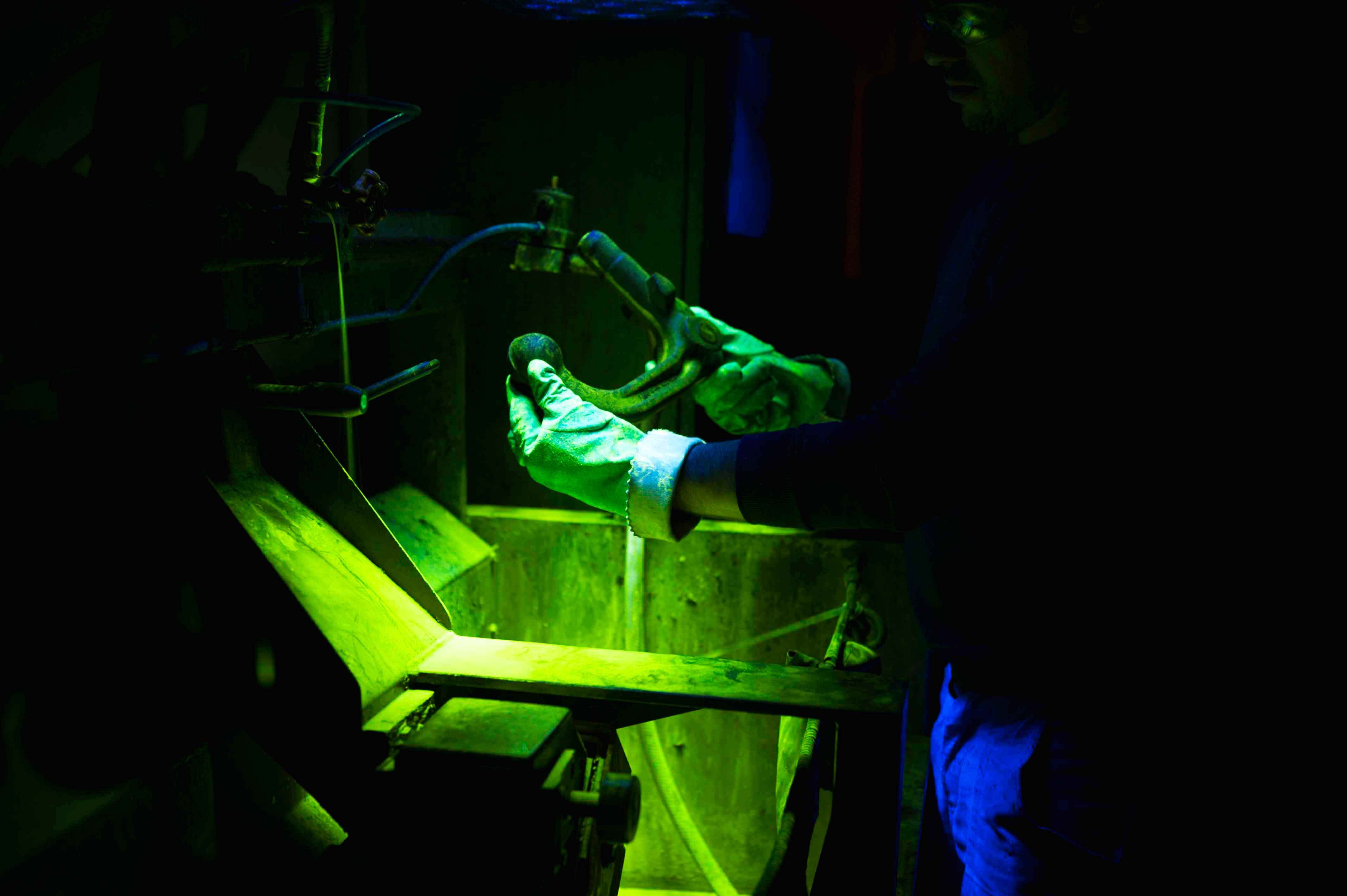
After the magnetization, magnetic powder (iron oxide powder) or a magnetic powder suspension is sprinkled or sprayed on the component to be tested. The ferromagnetic particles are attracted to the magnetic stray field or magnetic poles and accumulate around the crack. Since the magnetic field in the rest of the component is undisturbed, the particles accumulate only in the region of the crack. The crack is thus clearly visible on the surface of the component. To increase the contrast, a fluorescent dye is usually added to the powder. After the test procedure, the tested component must be demagnetized again.
To get cracks in the longitudinal as well as in the transverse direction, normally the two measuring principles of current and field flooding are under operation. If the current is conducted directly through the test piece, a magnetic field forms around the workpiece (circular around the component).


Magnetomotive Forces
If one creates a magnetic field using a U-shaped iron yoke and places the two poles on a rod-shaped ferromagnetic material, a magnetic field is formed inside the part (and outside as well). The field lines run in the direction of the rod axis. This type of magnetization causes magnetomotive forces. The field lines always go the way of the weakest magnetic resistance. If the bar is now split at one point or there is a crack on the surface or directly below it, the field lines are deflected and must leave the material. At the appropriate place, a magnetic leakage flux is formed.
To come back now to the subject of the introduction, cast iron components are slightly cheaper than wings of passenger aircraft in an assembled state …. For this reason, we at Brechmann-Guss take such missing parts “out of the race” – regardless of which material it is and in which industry our casting should go.