Measurement Technology
As exact as necessary…
is one requirement that all of customers have for our production – a requirement that must be checked and verified in our quality control room by measuring dimensions, angles, form, and surface quality, i.e. all aspects of the geometry of our castings. Above all, when examining a prototype or a piece being produced for the first time – the piece that brings together the customer’s needs and wants, the designer’s ideas, and the result of actual production – such measurements provide needed information about the quality of both our products and our processes. This information takes the form of measured, empirically obtained data, which provide the basis of our daily quality assurance work.
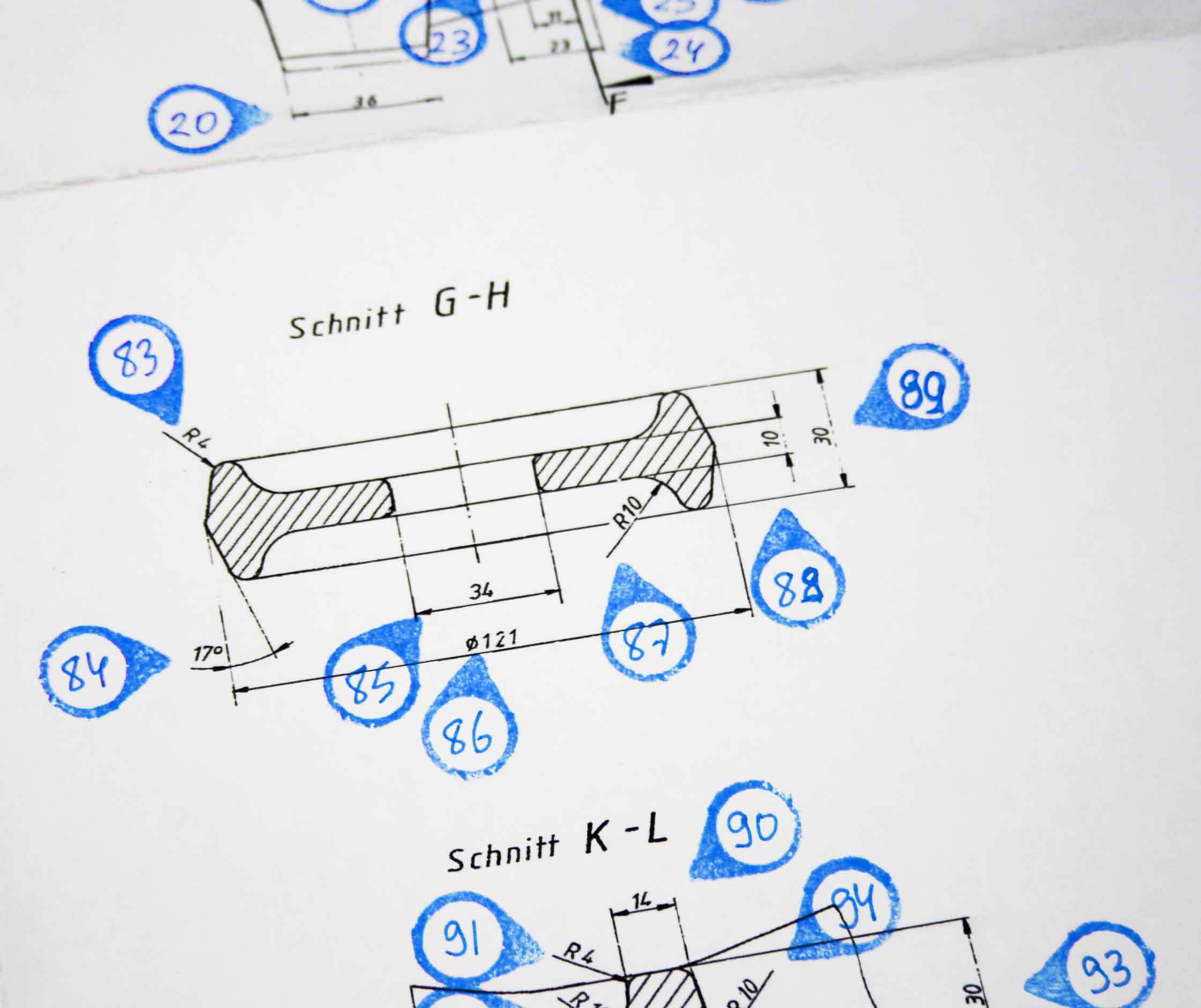
The turn of the millennium marked a massive turning point in previous technologies through the by now practically ubiquitous switch to 3D data files; however, this movement to CA-X systems also meant changes to the way that specifications and results are documented. Older designs and products have been based on physical paper drawings for more than 200. These drawings contain all of the most important information about a design, including outer dimensions and wall thicknesses at various points of the design, the diameter of any holes or apertures, and the distance from a reference edge to the centre point of a hole. Measurements were taken directly using callipers, radius gauges, scoring tools, and rulers; they were then entered into a table and compared, point for point, with the allowable tolerances according to industry standards. This time-intensive technique led to limiting – also in terms of limiting costs – the number of measurements taken to only the most necessary. Many regions remained unchecked in order to avoid expending unnecessary effort. Specifications such as “All unmarked radii > 5 mm”, which are advantageous for the requirements and abilities of sand casting with iron, or specifying minimum wall thicknesses and cross-sectional areas for flanges without giving a specific upper limit – all of these made the relationship between the foundry and the customer simpler over years of working together.


3D measuring
That has all changed with the “brave new world” of 3D-CAD. This system requires every aspect of a drawing (no matter how small) to be specified – regardless of whether it is important for the part’s functionality or not. The consequence is that specifications are given and must be measured which substantially increase the expenditure of time, energy, and cost – both for the foundry, as well as the manufacturer, and not least the end consumer. This means that creating a rational, sensibly limited set of measurements, possibly including 2D blueprints as an aid to the 3D computer file, represents a new challenge for designers. A measured evaluation of the flashy, colourful 3-D visualizations of measurement values adds a new dimension to the process – one that was previously unknown.
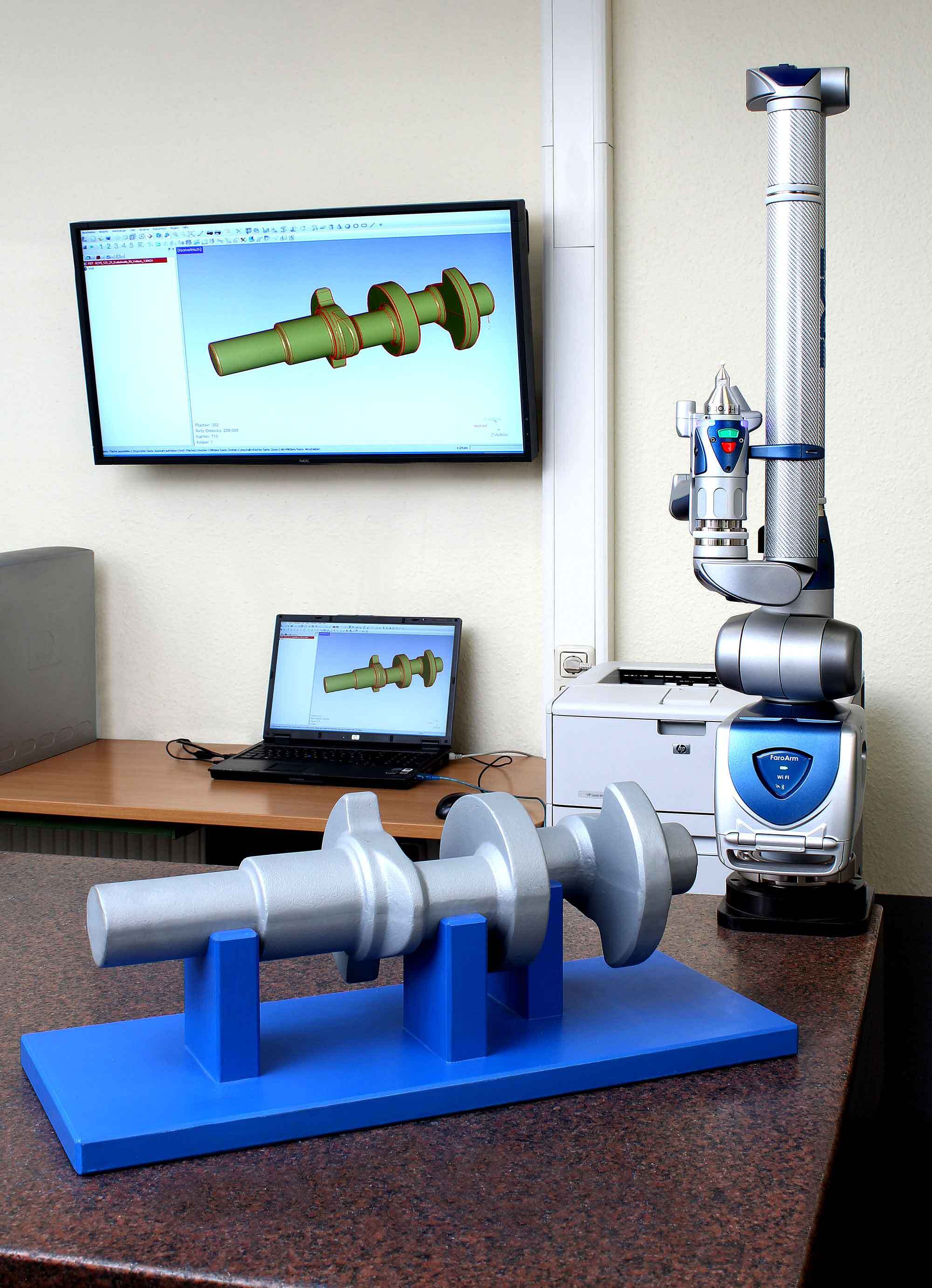
Today’s state of the art is coordinate-based measuring systems (either tactile or [laser-] optical). The system offers multiple advantages, not least among them the possibility of automating the testing process and so securing a high degree of repeatability of the results. From recording measurements, to the subsequent comparison and evaluation, and the eventual transfer of the test data to the central CAQ-system: all of this can be done automatically using “new” digital systems.
The measuring principle
The measuring principle behind this system differs significantly from that of traditional direct measuring techniques, such as with Vernier callipers or height gauges. The form of a component is described via geometrical elements (circles or lines, for example), which are matched to a set of previously determined three-dimensional points on the part surface. As an example: the machine will measure the feature “Outer Diameter” of a round workpiece by taking a series of measurements around the outside of the part at regularly spaced intervals. The software will then use the measured data to calculate the geometrical object “Circle”. The results from the measuring process will then correspond to the diameter of the calculated circle.

3D measurement systems
The basic principle of classic coordinate-based measurement does not differ significantly from that of 3D measurement systems. Both methods rely on a set of points measured on the real object, which they then use to calculate measurement values and describe shapes; these points are defined within a three-dimensional coordinate system. However, the collection method for the set of data points, the number of points collected, the analysis method, and the visualization of results, all vary considerably between the two methods.
3D-surface coordinated
Digitalization represents the first, and at the same time the most crucial, stage of optical 3-D measurement of a component. The term “digitalization” in this context is used to mean a description of a measured object via 3-D surface coordinated in space. In order to adequately capture the complexity of complicated shapes, as many points as possible should be recorded very closely together. The three-dimensional description of a flat surface with many (in some cases several million) points is therefore sometimes referred to as a “point cloud”. The closer the points are to one another, the more detail can be captured, and the more exact the representation of the surface will be.
3D-file
In the end, the computer generates a 3-D file from the point cloud of measurements, which is then compared to the original part file from the designer. Deviations appear in the visualization marked by colour (i.e. blue = over specs; red = under specs). The above-mentioned distinction between “important” and “unimportant”, which was previously familiar to anyone who knew how to use a set of callipers, now often falls by the wayside; this can lead to additional, entirely unnecessary time and effort spent on making changes, and additional time and production delays.